

close
Choose Your Site
Global
Social Media


Views: 0 Author: Site Editor Publish Time: 2026-08-25 Origin: Site


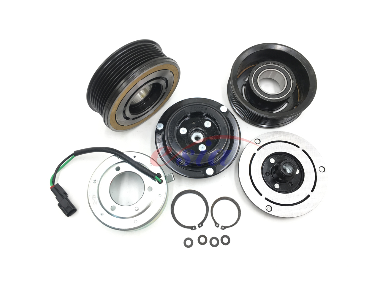
Every continuous belt-driven component steals power from your engine or motor. This parasitic power loss leads to premature wear. It also causes excessive fuel and energy consumption. A magnetic clutch solves this exact mechanical problem. We define it as a critical electromechanical component designed to transmit torque without direct mechanical linkages until engaged. It gives you total control over power distribution on demand.
Modern engineering requires moving beyond basic definitions to understand implementation realities. We must explore failure modes and technical evaluation criteria. This is crucial for commercial procurement and reliable system design. In this article, you will learn how these mechanisms operate under heavy loads. We cover everything from vehicle applications to complex industrial automation. You will discover practical methods to evaluate, source, and maintain these vital assemblies to prevent catastrophic downtime.
Magnetic clutches utilize electromagnetic fields to bridge the gap between a driving rotor and a driven armature, enabling on-demand power transmission.
The primary application is the AC compressor magnetic clutch, which decouples the compressor from the engine when cooling is not required, optimizing fuel efficiency.
Real-world reliability depends heavily on precise air gap calibration, thermal management of the electromagnetic coil, and accurate torque-to-load matching.
Sourcing requires evaluating voltage requirements, pulley groove configurations, and OEM-level compliance rather than relying solely on surface-level dimensions.
Understanding the mechanical anatomy of an AC Magnetic Clutch reveals why it acts as such an effective power-coupling device. The assembly relies on exact physical clearances and strong electrical fields. Engineers design these units to handle thousands of engagement cycles.
The system consists of three core components working in harmony:
Stator (Electromagnetic Coil): This is a stationary ring of tightly wound copper wire. It generates strong magnetic flux when energized. Manufacturers usually encase it in high-temperature epoxy to prevent moisture ingress.
Rotor (Pulley Assembly): The engine or motor belt drives this part continuously. It spins freely on a heavy-duty bearing when you disengage the system.
Armature (Hub/Friction Plate): Engineers mechanically link this directly to the compressor shaft. Flexible leaf springs hold it slightly away from the rotor.
The engagement sequence, often recognized by an audible "click," happens in milliseconds. Here is the exact step-by-step process:
Voltage applies to the stator coil through the control circuit.
The current creates a highly concentrated magnetic field around the copper windings.
This magnetic flux pulls the armature plate violently against the spinning rotor.
The force overcomes the physical resistance of the return leaf springs.
Friction locks the metal components together securely.
The assembly now transmits 100% of the rotational torque to the driven shaft.
You must understand one crucial implementation reality. Power transmission here is strictly binary. It operates either fully on or fully off. Gradual engagement or slippage is always a failure condition, not a feature. If the plates slip, they generate extreme heat. This heat quickly destroys the internal epoxy potting and ruins the assembly.
Modern internal combustion and hybrid engines operate under strict efficiency guidelines. The fuel economy mandate dictates power conservation across all subsystems. Continuous compressor operation remains completely unviable today. A typical air conditioning compressor drains significant horsepower. Letting it run when cabin cooling is unnecessary wastes costly fuel and increases emissions.
The AC Compressor Magnetic Clutch dynamically solves this load problem. It decouples the compressor shaft from the serpentine belt. This allows the pulley to freewheel without turning the internal pistons. The vehicle's Engine Control Unit (ECU) manages this delicate timing. It uses inputs from cabin thermostatic switches and system pressure sensors.
System dynamics require constant cycling. The clutch cycles on and off repeatedly during operation. It maintains exact evaporator temperatures this way. It also prevents catastrophic system freeze-ups and dangerous over-pressurization events. If system pressure spikes too high, a cutoff switch kills power to the stator immediately.
Engine load management also relies heavily on this engagement data. The sudden torque demand of a locking armature plate can bog down a small displacement engine. Modern ECU systems anticipate the engagement sequence. The computer slightly increases engine idle speed milliseconds before sending voltage to the coil. This prevents stalling and ensures a seamless driving experience. You barely notice the extra load during highway cruising, but it matters deeply at stoplights.
While automotive systems represent a massive market, electromagnetic coupling extends far beyond cars. Industrial sectors rely heavily on this technology for rugged, high-cycle operations.
Heavy equipment and agricultural machinery utilize these devices in PTO (Power Take-Off) systems. Operators use them to engage mowers, high-capacity water pumps, and auxiliary hydraulic accessories. These environments involve extreme vibration, heavy dust, and frequent shock loads. The clutch assembly must survive these brutal conditions without failing.
Manufacturing and automation sectors also depend on precise motion control. Rapid-cycling packaging equipment requires exact start-and-stop indexing. An AUTO AC Magnetic Clutch design inspires these industrial variants. You can stop a specific conveyor section without shutting down the primary drive motor. This maximizes production line throughput and minimizes energy spikes from motor restarts.
Commercial HVAC systems scale this technology for massive operations. Large-capacity chiller units and transport refrigeration trailers face fluctuating thermal loads. Supermarket refrigeration relies on large electromagnetic clutches to cycle massive twin-screw compressors. The design allows trucks to maintain freezing temperatures while traveling across long, hot distances.
Engineers face different design trade-offs when scaling these parts for industry. Below is a comparative chart detailing these operational differences:
Design Parameter | Automotive Application | Industrial & Heavy-Duty Application |
|---|---|---|
Torque Capacity | Standard (Matches passenger cabin AC displacement) | High (Engineered for massive PTO shock loads) |
Footprint Size | Compact (Must fit tight engine bays) | Bulky (Prioritizes massive heat dissipation) |
Voltage Systems | Typically 12V DC | 24V DC to 90V DC (Industrial bus systems) |
Cycling Frequency | Moderate (Thermostat driven) | Extremely High (Rapid indexing machines) |
Industrial variants prioritize immense torque capacity and rapid heat dissipation. They often use heavier leaf springs and larger friction surfaces. You will notice they trade the compact footprint of passenger vehicles for sheer durability and holding power.
Even the best components eventually degrade under severe operating conditions. Diagnosing the root cause of an AC compressor magnetic clutch failure requires patience and proper measurement tools. Swapping parts without investigating the failure mode usually leads to repeat breakdowns.
Air gap tolerances represent the single most critical metric in system health. Over time, the friction material on the armature plate wears down. This naturally widens the physical gap between the plate and the rotor. If the gap becomes too wide, the magnetic field simply cannot pull the plate across the void. The system receives voltage, but nothing engages. Conversely, if the gap sits too narrowly, continuous drag occurs when disengaged. This drag ruins the bearing and melts the internal seals.
Thermal overload, often identified by burnt coils, is usually a symptom rather than the root cause. Slipping plates generate extreme friction heat. This heat transfers directly into the stator core. It rapidly melts the protective epoxy sealing the coil. Once the epoxy degrades, the copper wire shorts out against the metal housing. You will measure zero resistance across the terminals when this happens.
Voltage drop issues also plague older setups. Corroded wiring harnesses or weak relays prevent full current from reaching the stator. Undervoltage means the magnetic field lacks the strength to hold the plate securely. The assembly slips under high pressure, mimicking a mechanical failure even though the clutch itself remains physically intact.
Continuous tension from the tight drive belt eventually degrades the rotor bearing. Bearing fatigue announces itself through an audible whining or grinding noise. If ignored, the bearing locks up entirely. A locked bearing snaps the serpentine belt and leaves the machine completely stranded.
Here is a quick troubleshooting reference table to help isolate common symptoms:
Observed Symptom | Most Likely Cause | Recommended Action |
|---|---|---|
Coil receives 12V, but no engagement | Excessive air gap or open circuit in coil | Measure air gap with feeler gauge; check coil Ohms. |
Loud grinding noise when AC is OFF | Rotor pulley bearing failure | Replace pulley bearing immediately to prevent belt snap. |
Clutch slips during acceleration | Low voltage or worn friction surface | Test supply voltage under load; inspect plate wear. |
Melted epoxy weeping from stator | Severe thermal overload (slippage) | Replace entire assembly; investigate underlying pressure issues. |
Replacing or specifying these parts demands rigorous technical matching. Relying solely on surface-level dimensions often leads to catastrophic system failures. You must evaluate internal specifications to ensure long-term durability.
Matching specifications to your exact use case requires checking three primary technical areas:
Static Torque Rating: You must verify the holding power. The static torque rating must exceed the maximum peak load of the driven shaft by at least 1.5x. This safety margin prevents high-RPM slippage during sudden engagement events.
Voltage and Current Draw: Always verify compatibility with the main system bus. Most mobile applications use 12V or 24V DC. You must also assess the amperage draw limits of existing relays and fuses. A high-torque coil might pull more amps than the factory wiring can safely handle.
Pulley Configuration: Geometry matters immensely. You need exact matching of the pulley diameter and the belt type. A 6-groove serpentine setup behaves very differently than a single heavy-duty V-belt. Incorrect diameters alter the final drive ratio, spinning the compressor too fast or too slow.
Quality indicators and trust markers separate premium manufacturers from standard aftermarket suppliers. Look specifically for ISO/TS 16949 certification when sourcing for automotive applications. This standard guarantees stringent quality control during manufacturing. Require transparent data on coil winding insulation. Class H insulation withstands significantly higher ambient temperatures, preventing premature thermal breakdowns. Look closely at the epoxy potting quality. It should appear uniform, without air bubbles or cracks.
Apply strict shortlisting logic during procurement. Reject suppliers who cannot provide exact air gap specifications or dynamic torque curves. You need actual engineering data, not just marketing claims. Prioritize manufacturers offering fully matched assemblies. Buying a pre-calibrated kit containing the coil, rotor, and armature eliminates installation guesswork. Piecemeal components rarely align perfectly, leading to immediate clearance issues upon installation.
The magnetic clutch serves as the decisive link between power generation and your mechanical application. It demands strict adherence to electrical and mechanical tolerances for long-term survival.
You must strictly monitor air gap clearances to prevent slippage and thermal overload.
Ensure your static torque rating exceeds system peak loads by a 1.5x margin.
Always verify voltage supply health before condemning a non-engaging coil.
Prioritize complete, pre-matched assemblies from ISO-certified manufacturers over piecemeal repairs.
Whether maintaining a fleet of utility vehicles or engineering a rugged industrial HVAC system, preventing premature failure relies on proper torque matching. Do not let parasitic power loss degrade your operational efficiency. Contact our technical sales team today with your specific voltage, torque, and dimensional requirements. We can provide a comprehensive engineering review and component specification tailored exactly to your equipment needs.
A: Use a precise feeler gauge between the armature plate and the rotor friction surface. Check multiple points around the circumference. Adjustment is typically done by adding or removing precision metal shims located directly on the compressor shaft beneath the armature hub.
A: While technically possible to rewind the copper wire, it is never recommended for commercial or automotive applications due to high reliability risks. Total stator replacement remains the accepted industry standard to ensure longevity and safety.
A: Known as "short cycling," this rapid clicking is rarely a clutch failure. It is typically triggered by low refrigerant levels, a faulty high/low pressure switch, or an overheating compressor. The system actively cuts power to protect itself from damage.
A: No. If the main compressor shaft turns smoothly by hand and the internal system holds pressure, you can usually replace the clutch assembly independently. This saves significant labor, as you do not need to recover or recharge the system refrigerant.


